Temperature Controlled DC Fan Circuit using Thermistor Circuit Diagram
Temperature Controlled DC Fan Circuit using Thermistor Circuit Diagram When the temperature rises its resistance is decreased and increases when the temperature is low. The other important component of this circuit is a transistor. we have used a BD139 transistor it is working as a switch for the fan in this circuit. This circuit is inexpensive and easy to build as it is using only a few components. The circuit for the temperature-controlled fan is rather simple. Three pins make up the LM35 sensor: VCC, GND and analog output pin. The Arduino 5V pin will be linked to the VCC pin. The analog output pin will be linked to the Arduinos A0 pin, and the GND pin will be connected to the GND pin.

In this article, you are going to learn about Arduino temperature controlled fan using DHT22 sensor and relay. We will use the DHT22 sensor to get the temperature value and we will print this temperature value on the LCD. Then we will check if the temperature value is greater than 35 or not, if the temperature will be greater than 35, then the
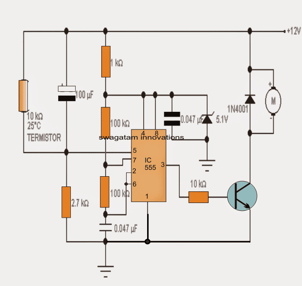
Simple Temperature Controlled DC Fan Circuit Diagram
Here in this temperature controlled dc fan project, a 10K NTC thermistor is used. To turn on the DC fan, we use an IC 741 op-amp as a voltage comparator. Its inverting input (pin 2) gets an adjustable voltage through the potentiometer while its non-inverting (pin 3) input gets voltage through a potential divider involving a 1KΩ resistor and
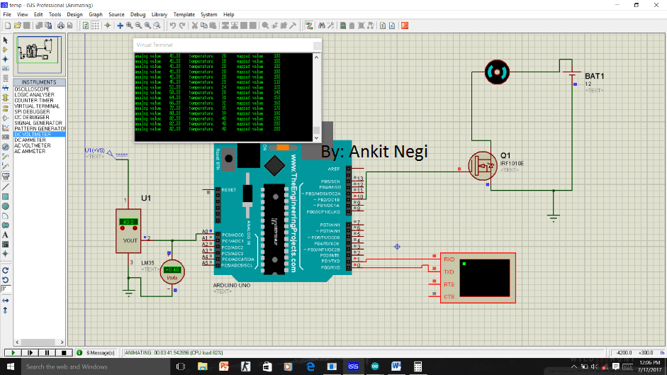
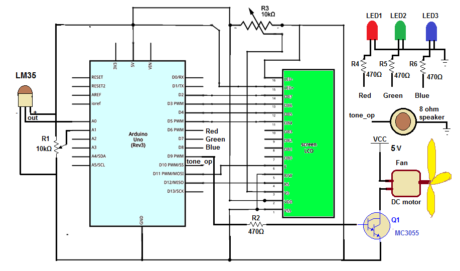
The second temperature controlled dc fan circuit project discussed below automatically senses the ambient temperature and adjusts the fan motor speed to keep the surrounding temperature under control. This automatic processing is done through an Arduino and a temperature sensor IC LM35. By: Ankit Negi. OUR OBJECTIVE: 1).

Temperature Controlled DC Fan Circuit Diagram
Temperature Controlled Fan Circuit Diagram. The complete circuit to build the temperature controlled fan using arduino and lm35 project is given below, we have used fritzing software for making most of the circuit diagrams. The fan and the plug were later added using photoshop. The diagram consists of an arduino,a relay, an lm35 sensor, an AC fan, and a plug.

The design of a circuit is very simple and it requires a less number of components. The BD139 transistor operates as a switch here. In addition to this, the temperature-controlled sensor uses the NTC thermistor to control the temperature. So when the thermistor receives the heat its resistance starts decreasing.